
Cargo ship – By Pixabay
This article analyses several energy storage technologies to be used in maritime transportation to reduce the pollution in port areas. In particular, the paper presents some alternatives to the use of batteries, which have demonstrated some performance limitations in marine environment. Supercapacitors, flywheels and superconducting magnetic energy storage are studied for their use in the power supply of vessels when manoeuvring close to the port. A real study case has been selected to define the energy storage requirements, and the three technological solutions are described in detail. Some design, modelling and operation details for the three scaled down prototypes developed are included in the paper. The demanding environmental marine conditions is a challenge on the project to marinize these technologies. Therefore, a containerized solution is preferred and described within the paper. Supercapacitors and a flywheel will be mounted on board of a vessel for their characterization under operational environment.
INTRODUCTION
In response to growing concerns about environmental pollution and fossil fuel consumption in the maritime industry, especially in port areas, electrifying propulsion systems and service loads has emerged as a frequently employed and effective approach to meet environmental guidelines. This has led to the development of complex shipboard microgrids, resembling terrestrial islanded microgrids, with high dynamic loads, intricate control, and power management systems. The integration of on-board Energy Storage Systems (ESS) has become imperative to fulfil power requirements and accommodate grid loads.
While initial industry efforts have focused on high energy density ESS solutions, other innovative energy storage systems options with unique capabilities remain underexplored. For most waterborne applications, deployments batteries are founded upon stablished battery technologies. However, there are other energy storage systems that may be useful for these applications in the future that have not yet been thoroughly investigated. This is the case of the named Fast Response Energy Storage Systems (FRESS), including Supercapacitors or Electrical Energy Storage System (EESS), Flywheels or Kinetic energy Storage System (KESS), and Superconducting Magnetic Energy Storage (SMES) or magnetic energy storage systems. Although they are currently used as a solution for certain applications where high power is needed, there are some others still without enough comprehensive attention. That is, for instance, the case of present and future ships, which require ESS to improve or even to allow certain operations. ESS have not been extensively implemented in waterborne application, where some peculiarities must be considered and explored (regarding lifecycle, operational temperature, deep discharging, toxicity, or environmental impact). FRESS systems could overcome some of these limitations, usually found in ESS based on batteries.
Furthermore, there is a great synergy combining different storage systems (hybridation) where a FRESS supports a battery to reduce its size (and consequently its impact) while increasing its lifetime by absorbing the fast cycles. FRESS will take care of short duration high power transients, while batteries will concentrate on long durations events which are more energetic. This complementarity allows FRESS to handle high-power, high-frequency loads, while high energy density ESS such as batteries can address long-term energy needs. Moreover, this solution decreases the possibility of thermal runaway in the batteries, increasing the safety.
FRESS also offers valuable attributes such as frequency regulation, voltage control, oscillation damping, voltage ride-through, and peak shaving, making them not only unique but also highly complementary to high energy density ESS like batteries or hydrogen. This paper is based on the developments of the European project POSEIDON, (grant agreement ID: 101096457 Topic: HORIZON-CL5-2022-D5-01-02) which main objective is to demonstrate the applicability of 3 innovative fast-response energy storage systems (FRESS), Supercapacitors, Flywheels and SMES, in waterborne transport, addressing their on-board integration, cost-competitiveness, efficiency and safety, in relevant environments. The activities carried out in the projects related to this topic HORIZON-CL5-2022-D5-01-02 (Innovative energy storage systems on-board vessels) are expected to result in a TRL 5 of energy storage systems, alternative to batteries, at the end of the project.
The article is divided into six main sections. Section II describes the use case and benefits of the proposed FRESS. Section III describes the design and characteristics of the kinetic energy storage system. Section IV details the design and characteristics of the supercapacitor-based storage system. Section V describes the design and characteristics of the SMES-based storage system. Section VI presents the containerized solution for the integration of FRESS. Finally, in section VI some conclusions of the study are presented.
Potential application of FREES on marine transportation
POSEIDON project analyses potential application of FRESS in waterborne applications. One of the most significative applications for the use of a FRESS in vessels is during the manoeuvring operations close to the port. In fact, the fuel powered mode is becoming restricted for vessels close to the port, to reduce the excessive pollution in port areas. In this sense, some solutions could be implemented: battery powered, fuel cell powered or FRESS powered modes. To define the most appropriate solution it is necessary to make a first analysis of the power level, energy range and number of cycles required by the system.
The paper includes the case study of a Ro-Ro (roll on – roll off) vessel from the Spanish company Baleària, dedicated to maritime transportation. Fig. 2.1 depicts a real image of this vessel. The main characteristics are presented in Tab. 2.1.
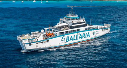
Figure 2.1. Actual image of the Baleària ferry where the FRESS system will be installed
 Table 2.1 Baleària Ferry Company Characteristics
The aim of this study is to define a suitable energy storage system for providing the energy required for the port approach and departure manoeuvres. The vessel is not allowed to use fuel propulsion or generators during these operations, neither to be connected to the electric grid at the port. As a result, the power profiles resulting of the approach and departure are presented in Fig. 2.2 and 2.3.
The port approach manoeuvre takes around 5 minutes and the port departure one a similar time. Additionally, the vessel makes around 12 trips per day or 30 minutes of duration. The peak power required for this operation is 500 kW and the energy consumption during the two cycles is in the range of 10 kWh.
Considering the power/energy ratio of this analysis, as well as the number of cycles required per year, a FRESS results an appropriate solution for this case, since the parameters of these technologies are within the data obtained.
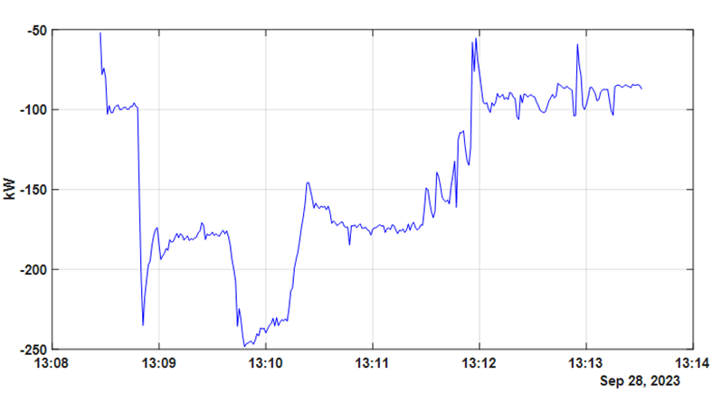
Figure 2.2 Power profile consumed by the motors during the port approach manoeuvre.
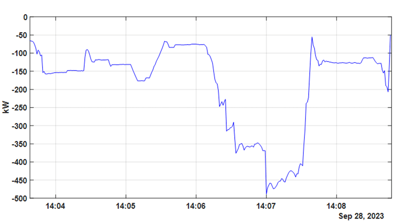
Figure 2.3 Power profile consumed by the motors during the port departure manoeuvre
POSEIDON project has the objective to develop scaled down prototypes based on the technologies of flywheels, supercapacitors and SMES, in order to validate experimentally their operation for this application. The following sections will describe the solutions proposed.
The Flywheel or Kinetic Energy Storage System (KESS)
Kinetic energy storage systems, more commonly named flywheels, are based on storing energy in a rotating mass, according to the equation E = ½ ·J · w2, where J is the mass moment of inertia and w its angular velocity [8][9]. The acceleration and deceleration of the mass is achieved by injecting and extracting power from an electric machine whose moving part rotates in solidarity (mechanical coupling) with the flywheel. The power of the electric machine determines the power of the storage system. In this way, power and energy are decoupled in the flywheels.
Regarding the design target power of the KESS, it is set at 20kW. This value, associated to the electric machine, is selected based on CIEMAT’s experience in the design of machines for this type of applications and because it is considered an appropriate value for a unitary module.
Among the different electrical machines available on the market, switched reluctance machines and permanent magnet machines are the most appropriate for this type of application. The switched reluctance machine (SRM) has been chosen for this application because it has lower losses than the magnet machine in the absence of torque, no demagnetization problems at high temperatures and lower cost, it is more robust in aggressive environments, and it does not depend on rare earths. The Switched Reluctance Machine (SRM) is characterized by the need to operate in conjunction with power electronics that control the sequential activation of each of its phases. The operating principle of a SRM is based on minimizing the energy of a magnetic circuit, i.e. reducing the reluctance of the circuit. Following the principle of minimum reluctance search of the magnetic circuit the rotor tries to rotate counterclockwise until this position is reached (position of maximum alignment). When the minimum energy of phase A is reached, the magnetic forces try to keep the rotor in this position in compliance with the above principle. At that moment, the power supply of phase A must be turned off, energizing the next phase, making the rotor rotate. Once this switching of the phases is done, continuous motion is generated in the SRM.
Power and Control System
The topology of the power electronic converter used to drive this machine is shown in the figure 3.4. In this case it is used a H-bridge topology. The converter allows three different voltage levels to be applied to each of the phases of the machine: +UDC to increase the current or -UDC or 0V to decrease the current. In this way it is possible to regulate the level of current through the phases, and thus control the torque and power exchanged by the machine. Another important aspect of the converter is that it must be bidirectional in power to allow charging and discharging of the kinetic storage system.
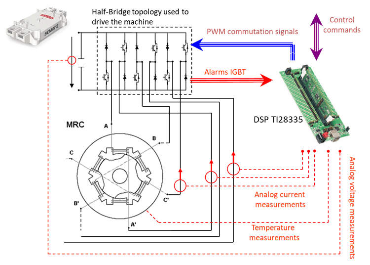
Figure 3.4. Schematic diagram of H-bridge power converter driving an SRM
The energy of the kinetic storage system is decoupled from the power and depends linearly on the moment of inertia of the rotating mass and the square of the rotational speed. In this case, a solid high-strength forged steel cylinder will be used as a flywheel with an operating speed range of 8000-10400rpm. In this operating speed range, the useful energy of the system is 1.1kWh. Fig. 3.5 shows a CAD drawing of the electrical machine and the flywheel, as well as the parts it consists of.
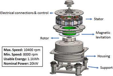
Figure 3.5. Schematic diagram of H-bridge power converter used to power the SRM phase A
The Solution Based on Supercapacitors (EESS)
The storage system based on supercapacitors (SCs) is mainly composed by a bidirectional DC/DC converter connected to a rated 750V DC line where several SC modules are series connected. A conceptual scheme of the storage system is shown in Fig. 4.6. while Fig. 4.7 shows an example of DC storage made out by series connected SC modules.

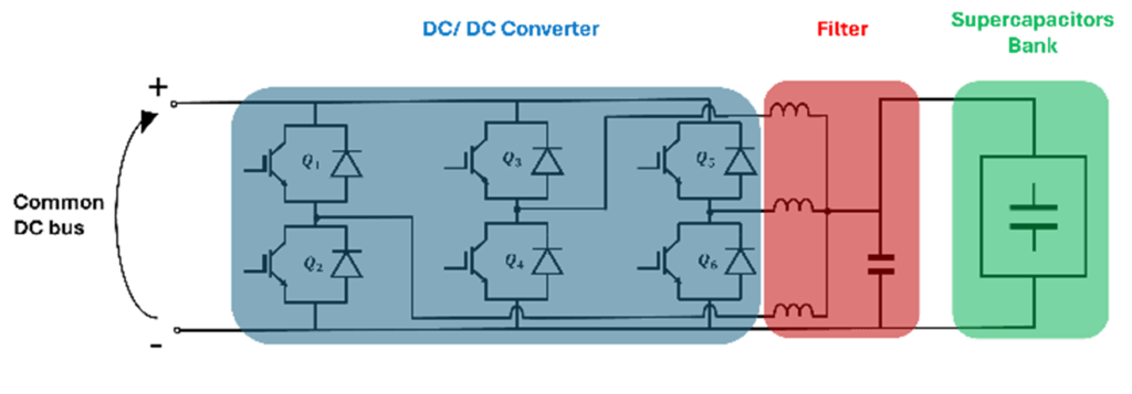
Figure 4.6. Schematic diagram of EESS with DC/DC converter
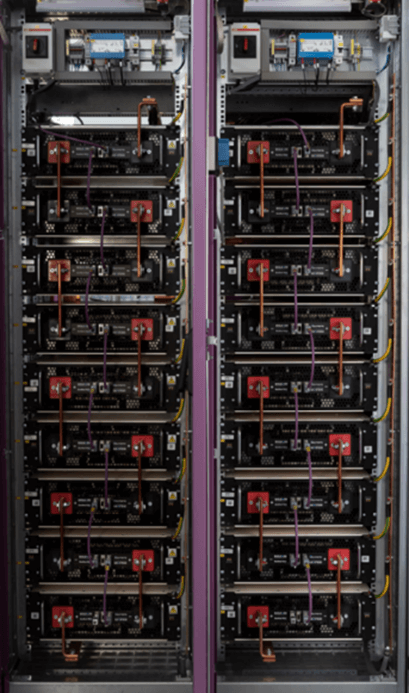
Figure 4.7. Series connection of SC modules
The system selected has a voltage oscillation is between 750 and 300V, providing an amount of useful energy of 3MJ. The system is able to provide a maximum power of 120kW when the system is fully charged.
The DC/DC converter will initially charge the SC bank before operation up to a fixed charging voltage, maximum 750V; during the operation, the SC bank will be discharged/charged following the power or current reference delivered by the main control system, indicated as “Energy Dispatcher”. The controller assures that during the operations, the SC voltage remains constrained between minimum (≥ 300 V) and maximum (≤ 750 V) voltage. This voltage excursion allows to exchange a net energy of 84 % of the total energy stored in the SC bank. The SC bank must not be discharged completely during operation, because the more the voltage drops, the more the current through the supercapacitor through a normally closed contactor. The resistor is sized to dissipate all the SC energy. It assures an exponential decay of the SC voltage, so that the approach of zero voltage is slowly achieved. This will protect individual SC cells, which are connected in series, from voltage inversion that could happen if the SC voltage is abruptly brought to zero.
The control system takes care of controlling the current delivered as well as to perform diagnostic and protection of both the DC/DC converter and SC bank.
Some operation results related to the dynamics of the SC system will be added to the final version of the paper.
A solution based on SMES
A typical SMES (Superconducting Magnetic Energy Storage) system comprises three primary components: a superconducting magnet along with its cooling system, and the power conditioning system (PCS), serving as the interface between the magnet and the power grid.
This system stores electrical energy within the magnetic field generated by the Direct Current (DC) flowing through the superconducting coil, which has undergone cryogenic cooling to a temperature below its superconducting critical temperature. Typically, when current flows through a coil, the electrical energy dissipates as heat due to wire resistance. However, if the coil is constructed from a superconducting material like mercury or vanadium and is in its superconducting state (usually at an extremely low temperature), it exhibits zero resistance, enabling the storage of electrical energy with minimal losses.
System optimization is a complex task which requires various iterations. Typically, the main constraints imposed on a SMES come from the power application, i.e. the required energy and power, the DC link voltage, and the dynamic response. However, there are additional constraints for its use in waterborne applications, which could be categorized in three:
- Physical: temperature, humidity and salinity levels.
- Mechanical: relative movement to the ground, which produces linear and angular accelerations, or vibrations.
- Electromagnetic: Limit for magnetic field value for EMI compatibility and people safety.
Tab. 2 provides a summary of these constraints, and the limit values established for compliance in the POSEIDON project based on existing regulations for ESS, and electrical machines in vessels, and the use of the high magnetic field equipment near people.
Electromagnetic Design
The electromagnetic characteristics of the SMES depend on the magnet’s geometry, the properties of the superconducting tape, and the operating conditions. Choosing the ultimate geometry involves maximizing the specific energy per meter of superconducting tape, usually resulting in coils with larger diameters. However, in the case of the POSEIDON SMES, the maximum dimensions were restricted by the physical limitations of the intended application. Consequently, the coil size was predetermined, and its specific dimensions can be found in Tab. 2, leaving the separation distance between the pancakes as the sole variable available for optimization.
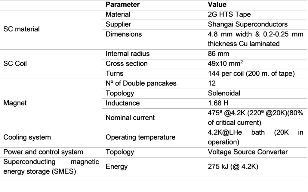 Table 5.2. Main parameters of Poseidon SMES
A parametrized COMSOL model was developed for the optimization process. In the case of HTS magnets the angle dependence of the critical current of the HTS tapes makes it necessary to evaluate the load curve not only in the inner radius, but in all the magnets. The distance between coils decreases from 15 mm. in the outer coils to just 2 mm. between the inner coils, yielding a maximum energy of 275kJ.
The cooling system will employ flow refrigeration, utilizing forced convection of helium gas for cooling. The rationale behind opting for this system lies in its capacity to function autonomously, its cost-effectiveness, compact design, and the ability to dissipate heat locally. Moreover, it offers the flexibility of operating within a range of temperatures, from 4.2K to 77K. This concept has already undergone successful testing in other superconducting applications and is referred to as the Cryogenic Supply System (CSS).
Power and Control System
The selected PCS is a Voltage Source Converter formed by a Gride Side Inverter based on IGBTs and a dc-dc chopper (see Fig. 5.8). The control strategy is based on keeping a constant voltage across the dc-link capacitor. This option allows the exchange of power in the four quadrants as can be selected from 0 to 360º. This solution is characterized by an intermediate value of Total Harmonic Distortion (THD) and also a medium ripple in the voltage applied to the coil leading to moderate a.c. losses.
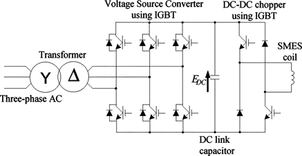
Figure 5.8. Voltage Source Converter PCS schematic
Containerized solution for the integration of FRESS
FRESS systems will be integrated in the future in a common in a common infrastructure that, at this time, is expected to be a 20’’ maritime container. This container will be embarked and connected to the ship to test the FRESS systems, which are protected from sea environment with this solution. In addition, the container will provide a supporting structure for all equipment, especially for KESS system.
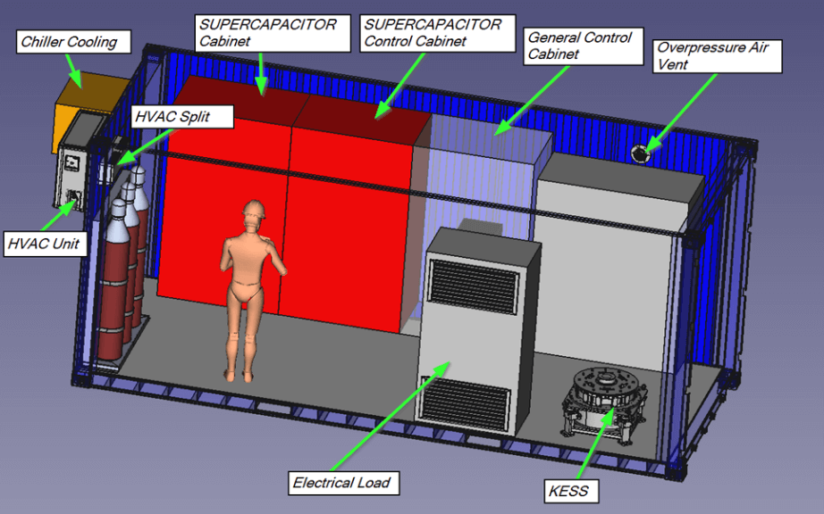
Figure 6.9. Arrangement of the FRESS inside the containerized solution
One of the main objectives of introducing a set of fast-response energy storage devices is to better adjust the requirements of power and energy from the load to the energy storage system and to reduce the battery ageing by sharing the power demanded by the electric load on board.
The power contribution of each subsystem is determined by means of a control optimization algorithm, which takes into consideration, in one hand, measurements of the operation variables of the different storage systems, such as: temperature, current and state of charge (SoC) of the three fast-response devices. One of the main missions of this phase will be then to test this control algorithm.
On this case, it is difficult to directly connect the containerized solution directly to the ship due to the need of transform a part of the ship’s electrical system, which is outside the scope of this project. For this reason, the container will only absorb power from a dedicated diesel generator of the ship, through an isolation converter, to charge FRESS systems. The discharge of FRESS is done by means of a heater incorporated into the container where the power dissipated is imitated by the control system according to real based power consumption profiles. Fig. 6.9 presents a CAD of the FRESS system inside the containerized solution.
High-level simulation model
With the purpose of simulate all systems together working inside the container, a high-level model is being developed. So far, this model only accounts for thermal modelling of the container to sizing the air conditioning system.
For this purpose, an AmeSIM model is developed to account for heat losses between container internal air and external conditions. This model includes sun heat radiation and convection factors for both internal and external surfaces. Internal heat gains and air conditioning are simply modelled as a single heat flow at this stage.
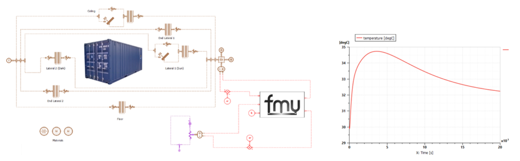 Figure 6.10. High Level simulation model and temperature after an emergency discharge
On the preliminary simulations there is identified an event that is critical for the thermal behaviour of the system. This event consists of an emergency shut-off of the system, where for safety issues the supercaps energy is discharged totally in a ceramic disk resistor. This disk resistor is heated in less than two minutes and then a slow cooling by convection starts for about six hours.
To study this effect, a disk resistor model is developed in Modelica, and then is integrated as an FMU into the AmeSIM model, as shown in figure 6.10. After developing the model and validating it against the literature, a final validation using the simplified cooling correlations from the ceramic disk resistor manufacturer was performed.
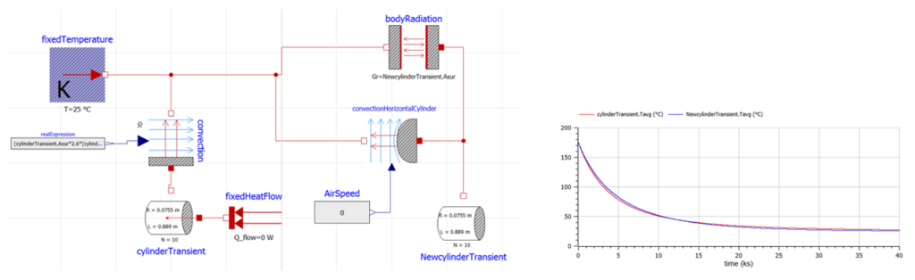
Figure 6.11. Validation of ceramic disk resistor model
Another custom component of the container that needs a specific thermal model is the load resistor. This resistor will emulate the electric load supplied by the FRESS to the ship. The resistor takes air from outside of the container, dissipate power by heating the air, and is exhausted to the outside again. Then, the only heat introduced inside the container is through the resistance cabinet walls. It is difficult to predict how much heat is introduced into the container because there are too many variables affected, such as: power profile, radiation heat inside the load resistor cabinet, insulation, air conditions, etc… For this reason, a simulation model is adequate to be developed.
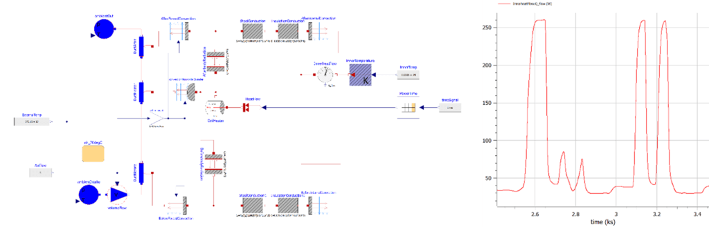
Figure 6.12. Load resistor model and heat gain on the container
Conclusions
This paper presents the design and fabrication of a fast response energy storage system for marine applications. Three different technologies with similar characteristics are studied to find out which of them is best suited to the present application. POSEIDON ambition is to assure a cost-effective deployment of ESS in the maritime industry to guarantee a rapid transition to an efficient and sustainable mode of transport. POSEIDON will contribute to this objective by exploring the applicability of FRESS to different waterborne segments and by developing an on-board demonstrator, testing and validating 3 FRESS systems in a relevant marine environment.
The final objective is to minimise or even eliminate the use of diesel power units during manoeuvres in port, the duration of which on short-haul vessels is approximately a few minutes. However, on this type of ship, the number of times per day that this type of manoeuvre is necessary is remarkably high. The characteristics of the storage systems proposed (fast response, high power and low energy) are very admirably adapted to this type of manoeuvres according to the power profile shown in the paper. We would like to extend our heartfelt gratitude to BALEARIA for generously providing us with the actual data on the ferry’s power consumption during its port manoeuvres. This valuable information has been instrumental in our analysis and understanding of the energy dynamics involved in these operations.
In the final version of the paper, conclusions will be drawn on the power and energy storage required to cover the power profile demanded and whether an additional higher energy storage system (e.g. batteries) is necessary to cover the needs. In this case the batteries would provide a more or less constant power and the proposed technologies would provide the high peak power (short time) to extend the lifetime of the batteries. In order to decide which is the most suitable storage solution, an economic analysis will be carried out to evaluate the different options taking into account the loss of battery capacity. On the other hand, complex Multiphysics simulations are used to develop and integrate all the systems together using FMU technology.
For more detailed information, you can read the full paper published in Zenodo repository.
This paper is co-authored by Ana Orduña Gargallo, Basilio Puente Varela, Carlos Gil Boronat, Carlos Hernando, Gustavo Soriano Navarro, Marcos Lafoz, María Dolores Fernández Ballesteros and Riccardo Testa.